Arduino powered Christmas LED Strip


This next project is just in time for the holiday season, though it is really my fiddling with the code that came with the libraries for a 32 LED strip from Adafruit. Last year I had bought a single 1 meter 32 LED strip to play around with (video), but this year I decided to go with a 5 meter 160 LED strip to place outdoors for the Holidays.

Materials needed:

  • LPD8806 32 RGB LED Strip from Adafruit I implemented this outdoors with a full roll of 160 LEDs (5 orders)
  • Female DC Power adapter (I used this one also from Adafruit)
  • 5V 10A power supply
  • Arduino Uno
  • 4-pin JST SM Receptacle (optional)
  • Jumper wires – male/male and female/female (optional)

Simply follow the instructions in the Adafruit tutorial. If you don’t order a full roll, you will need to be able to solder a surface mount in order to attach the wires needed for the LED strip. Last year, I had stripped off one end of some jumper wires, soldered them to the LED strip as outlined in the tutorial above, then wrapped the end in some black electrical tape.

Surface mounts

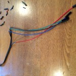
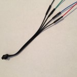
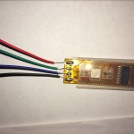
This year however, I bought a whole roll and therefore used a 4-pin JST SM Receptacle to connect to the plug on the end of the LED Strip. To make the project easier to assemble and disassemble, I stripped one end of the JST SM connector, and soldered that to one end of a female/female jumper wire, as below.

IMG_0582 IMG_0584

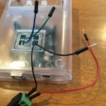
Once the Arduino is mounted in a case, and male/male jumper wires are plugged into the correct pins, it looked like this, which I then connected the female jumper wires on the JST SM connector appropriately and then boxed it up to protect it from the elements.

IMG_0581

Seperately, I mounted the LED strip to our deck railing (with tape) – because we’re using the JST SM connector, it’s easy to disconnect the Arduino and power supplies in bring them in if the weather is bad, leaving the LED strip in place.

Now, because the product description says the LED strip “comes with a weatherproof sheathing” I decided to but it to the test of Colorado weather in December, as seen in the video above.

Finally the code:

/*
 * LED Strip - Christmas Theme
 *
 * by: Keith Kay
 * 12/20/2014
 * CC by-sa v3.0 - http://creativecommons.org/licenses/by-sa/3.0/
 * https://keithkay.com
 *
 * This sketch displays a bitmap or series of bitmaps on a 8x8 LED matrix, and implements the following
 * functionality:
 * - supports a variable number of frames as defined by the constant "frames"
 * - use of a potentometer to control the frame rate
 *
 * Portions of this code from:
 * "strandtest" by Adafruit - https://github.com/adafruit/LPD8806
 *
 */

#include "LPD8806.h"
#include "SPI.h"

int i,j;

// Number of RGB LEDs in strand:
int nLEDs = (32 * 5); // or 160, each meter has 32 LEDs, and I use this code for a 1 meter strip as well, so I just change the # of strips here

// Chose 2 pins for output; can be any valid output pins:
int dataPin  = 2; // blue wire
int clockPin = 3; // green wire
LPD8806 strip = LPD8806(nLEDs, dataPin, clockPin);

void setup() {
  // Start up the LED strip
  strip.begin();

  // Update the strip, to start they are all 'off'
  strip.show();
}

void loop() {
  
  colorChase(strip.Color(127,   0,   0), 25, 1, 1); // Red
  colorChase(strip.Color(127,   0,   0), 25, -1, 1); // Red
  colorChase(strip.Color(  0, 127,   0), 25, 1, 1); // Green
  colorChase(strip.Color(  0, 127,   0), 25, -1, 1); // Green
  
  colorWipe(strip.Color(127,   0,   0), 5, 1, 1);  // Red
  colorWipe(strip.Color(  0, 127,   0), 5, -1, 1);  // Green
  colorWipe(strip.Color(127,   0,   0), 5, 1, 2); // Red
  delay(1000);
  
  alternateBlink(500, 50);
  fadeRedtoGreen(100);
  delay(200);
}

/* Sketch functions */

// Chase one dot down the full strip.
void colorChase(uint32_t c, uint8_t wait, int dir, int interval) {
  int i;

  // Start by turning all pixels off:
  for(i=0; i<strip.numPixels(); i++) strip.setPixelColor(i, 0);

  // Then display one pixel at a time:
  if (dir == 1) {
    for(i=0; i<strip.numPixels(); i += interval) {
      strip.setPixelColor(i, c); // Set new pixel 'on'
      strip.show();              // Refresh LED states
      strip.setPixelColor(i, 0); // Erase pixel, but don't refresh!
      delay(wait);
    }  
  } else {
    for(i=(strip.numPixels()-1); i>=0; i -= interval) { // We take one off the value to eliminate a 'double flash'
      strip.setPixelColor(i, c); // Set new pixel 'on'
      strip.show();              // Refresh LED states
      strip.setPixelColor(i, 0); // Erase pixel, but don't refresh!
      delay(wait);
    }     
  }

  strip.show(); // Refresh to turn off last pixel
}

// Fill the dots progressively along the strip.
void colorWipe(uint32_t c, uint8_t wait, int dir, int interval) {
  int i;

  if (dir == 1) {
    for (i=0; i < strip.numPixels(); i += interval) {
      strip.setPixelColor(i, c);
      strip.show();
      delay(wait);
    }
  } else {
    for(i=(strip.numPixels()-1); i>=0; i -= interval) { // We take one off the value to eliminate a 'double flash'
      strip.setPixelColor(i, c);
      strip.show();
      delay(wait);
    }
  }
}

void alternateBlink (uint8_t wait, int duration) {
  uint32_t stripColorArray[strip.numPixels()]; // We need somewhere to store the LEDs
  uint32_t pixelTest;
  
  for (i=0; i<strip.numPixels(); i++) {
    stripColorArray[i] = strip.getPixelColor(i);
  }
  
  // first pass thru to turn off alternate pixels
  for (i=0; i<strip.numPixels(); i += 2) {
        strip.setPixelColor(i, 0); // Erase pixel, but don't refresh!
  }
  strip.show();
  delay(wait);
  
  // now keep passing thru alternating blinks
  for (j=0; j<duration; j++) {
    // pass thru the strip and check if the pixel is on or off and flip accordingly
    for (i=0; i<strip.numPixels(); i++) {
      pixelTest = strip.getPixelColor(i);
      if (pixelTest == 0) {
        strip.setPixelColor(i, stripColorArray[i]); // restore the color from the array
      } else {
        strip.setPixelColor(i, 0); // erase pixel
      }
    }
    strip.show();
    delay(wait);
  }
}

void fadeRedtoGreen(uint8_t wait) {
  for (i=0; i < 127; i++) {
    for (j=0; j < strip.numPixels(); j++){
      strip.setPixelColor(j, 127-i,i,0);
    }
    strip.show();
    delay(wait);
  }
}  
Arduino 8×8 LED Matrix Multiframe Display

This project is an 8×8 LED Matrix bitmap driven display. One day while shopping on Adafruit for parts for a different project, I became fascinated with LED Matrixes they have for sale, and had a number of ideas for projects including a one letter at a time ticker-tape, and this project which is inspired by the old-fashion flip books like ones I would make in the corner of my notebooks when bored in class. I liked the notion of the challenge of having to design graphics that could only be represented in an 8×8 display. There’s something nostalgic about it. At any rate I hope you enjoy making this, and would love to see what bitmaps you come up with if you feel like sharing them.

What you’ll need for this project:

  • Arduino Uno
  • Medium breadboard
  • 8×8 LED Matrix (I used this one from Adafruit, but did not solder on the backpack yet)
  • Potentiometer (I used a 10k)
  • 8 1k Ω resistors
  • 18 jumper wires
  • 8 small pieces of hookup wire, trimmed (or additional jumper wire if you prefer)

I faced two main problems in getting this project to work. The first was figuring out which PINs lit up which rows and columns on the matrix. It turns out I couldn’t find a “standard” pin-out diagram, but I noticed from the picture on Adafruit for the part only half the pins on each side had a resistor, so that’s how I wired mine up. From there I went through the process of powering the matrix pin by pin to figure out the set up.

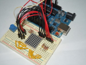
Once you have it wired up, it should look something like this:

Finished 8x8 LED Matrix Wiring

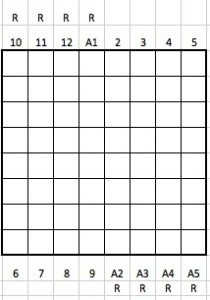
I am using A0 for the pot input (you will also need to connect it to a GND and 5v), and A1 to A5 correspond to digital output 15 to 19 (the Arduino analog pins can also be used as addition digital pull up resistors.) The wire diagramming tool I use didn’t have the graphic for the LED matrix, so I mapped the Arduino pins to the matrix below. The ones with an “R” need to have a resistor between the Arduino pin and the matrix pin.

8x8MAP

You can test your wiring with this simple sketch that will light up one LED at a time, then progress column by column row by row. If the LEDs are not lighting up in order, then change the order in columnPins and rowPins until they do.

const int columnPins[] = { 6, 7, 8, 9, 2, 3, 4, 5 };
const int rowPins[] = { 15, 12, 11, 10, 19, 18, 17, 16 };
int row;
int col;

void setup() {

  for (int i=0; i<8; i++) {

    // set each pin to output
    pinMode(columnPins[i], OUTPUT);
    pinMode(rowPins[i], OUTPUT);

    //ensure each LED is off
    digitalWrite(columnPins[i], HIGH);
    digitalWrite(rowPins[i], LOW);

  }  
}

void loop() {

  for (row = 0; row < 8; row ++) {
    digitalWrite(rowPins[row], HIGH);
    for (col = 0; col < 8; col++) {
      digitalWrite(columnPins[col], LOW);
      delay(100);
      digitalWrite(columnPins[col], HIGH);
    }
    digitalWrite(rowPins[row], LOW);
  }
}

The second issue was the time it takes, and the likelihood of making a mistake, in designing bitmaps by hand in the Ardunio sketch, 0 by 1. Especially since my goal was to make multi-frame movies. My solution to this was to develop a Processing program that would allow me to visually design each frame and save it to a file, which is described in a separate post.

Finally, load the following code into your Arduino sketch, upload to your Arduino board, and be sure to add your own set of bit maps (though you can use the one below in the code of course). This code can also be found on github along with a few example bitmaps.

/*
 * LED Matrix Bitmap Display v2
 *
 * by: Keith Kay
 * 11/27/2013
 * CC by-sa v3.0 - http://creativecommons.org/licenses/by-sa/3.0/
 * https://keithkay.com
 *
 * This sketch displays a bitmap or series of bitmaps on a 8x8 LED matrix, and implements the following
 * functionality:
 * - supports a variable number of frames as defined by the constant "frames"
 * - use of a potentiometer to control the frame rate
 *
 * Portions of this code from:
 *
 * “Arduino Cookbook, Second Edition"
 * by Michael Margolis with Nick Weldin (O’Reilly). Copyright 2012 Michael Margolis, Nick Weldin,
 * 978-1-4493-1387-6
 *
 */

// Note that if you are using Keith's "Processing Bitmap Generator for Adruino" you need to move the "frames"
// declaration up before the array, as it will be the last thing written to your bitmap file.

// <-- Copy and paste your bitmap array beginning here, or you can write it from scratch -->>

const int frames = 16; // Constant defining the number of frames

byte imgFrame[frames][8] = {
{   B11111111,B10011001,B10011001,B11111111,B11100111,B11000011,B11011011,B11111111}, // Each row here represents one frame
{   B11111111,B10011001,B10011001,B11111111,B11100111,B11000011,B11011011,B11111111},
{   B11111111,B11111111,B10011001,B11111111,B11100111,B11000011,B11011011,B11111111},
{   B11111111,B11111111,B11111111,B11111111,B11100111,B11000011,B11011011,B11111111},
{   B11111111,B11111111,B10011001,B11111111,B11100111,B11000011,B11011011,B11111111},
{   B11111111,B10011001,B10011001,B11111111,B11100111,B11000011,B11011011,B11111111},
{   B11111111,B10011001,B10011001,B11111111,B11011011,B11011011,B11000011,B11111111},
};

// <-- End copy and paste. Make sure you overright the array already here -->>

// define the constants used for sensor / emitter pins
const int columnPins[] = { 6, 7, 8, 9, 2, 3, 4, 5 };      // array holding the pin numbers of the rows
const int rowPins[] = { 15, 12, 11, 10, 19, 18, 17, 16 }; // array holding the pin numbers of the columns
const int potPin = A0; // potentiometer 

// define variables used for readings and programatic control
int row;
int col;
int potVal;
int frameDelay = 0;
int currentFrame=0;

void setup() {

  for (int i=0; i<8; i++) {

    // set each pin to output
    pinMode(columnPins[i], OUTPUT);
    pinMode(rowPins[i], OUTPUT);

    //ensure each LED is off
    digitalWrite(columnPins[i], HIGH);
    digitalWrite(rowPins[i], LOW);

  }  
}

void loop() {

  potVal = analogRead(potPin);    // read the voltage on the pot
  frameDelay = map(potVal, 0, 1052, 1000, 50); 

  if (currentFrame < frames) {
    show(imgFrame[currentFrame++], frameDelay);
  } else {
    currentFrame = 0;
  }
}

void show( byte * image, unsigned long duration) {

  unsigned long start = millis();        // begin timing the animation
  while (start + duration > millis())    // loop until the duration is reached
  {
    for (row = 0; row < 8; row++ )
    {
      digitalWrite(rowPins[row], HIGH);  // connect a whole row to +5v
      for (col = 0; col < 8; col++)
      {
        boolean pixel = bitRead(image[row], 7-col);
        if (pixel == 1)
        {
          digitalWrite(columnPins[col], LOW);  // connect column to grnd
        }
        delayMicroseconds(300);    //small delay for each LED
        digitalWrite(columnPins[col], HIGH);  // disconnect column from grnd
      }
      digitalWrite(rowPins[row], LOW);  // disconnect a whole row
    }
  }
}

When it’s finished you should be able to load different bitmaps and display them, as these examples show.


Processing Bitmap Generator for Adruino

bitmap_gen1A while back, I had purchased an 8X8 LED Matrix from adafruit, and while it comes with a multiplexer you solder on, before I took the easy route I wanted to wire it up the hard way so I would understand how it worked. And while there are plenty of tutorials and examples for Arduino out there, they presume you have a bitmap ready. And that is fine in terms of getting the matrix working, but in terms of getting it do something interesting, that would require a series or array of bitmaps, and rather than trying to sit down and write out a series of 0s and 1s in a text editor, I decided to make an editor in Processing which would do that work for me.

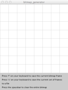
When run, the Processing code will display an 8X8 grid (shown right), each square of which is clickable. You can either save a frame, then clear the screen and draw the next frame, or save all the frames currently in memory to a file. As the code is currently written, each time a frame is saved to memory, a JPG file is also written to the [project folder]/bitmaps directory for testing purposes. This can be removed by commenting out this line of code:

saveFrame("bitmaps/bitmap-####.jpg");

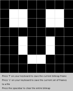
For example, if we create two frames that look like the images below:
happy_creepercreeper

The resultant file saves the bitmaps as an array called imgFrame, where each row in the array represents one frame. Note that in the code all the “rows” of a frame will be on one line to take less space, I have inserted a return here so you can visualize the creepers:

byte imgFrame[frames][8] = {
  B11111111,
  B10011001,
  B10011001,
  B11111111,
  B11100111,
  B11000011,
  B11011011,
  B11111111},
{
  B11111111,
  B10011001,
  B10011001,
  B11111111,
  B11011011,
  B11011011,
  B11100111,
  B11111111};

const int frames = 2;

The last line of the file declares a constant that defines the number of frames for use in your Arduino sketch that makes use of the bitmap. You will need to paste both the bitmaps and constant declaration into your Arduino sketch to make it work.

You can copy the code for this project, or you can download it from github and there are also a few example bitmaps in the bitmaps folder.

/*
 * Bitmap generator for an 8x8 LED matrix
 * by Keith Kay
 * 7/6/2013
 * CC by-sa v3.0 - http://creativecommons.org/licenses/by-sa/3.0/
 * https://keithkay.com
 *
 * portions of this code modified from:
 * Two-Dimensional Arrays - Example: 2D Array of Objects
 * http://processing.org/learning/2darray/
 *
 */

/* Declare our variables */
Cell[][] bitmap;          // 2-dimensonal array used to store the bitmap
PrintWriter bitmapOutput; // declare an instance of PrinterWriter, a processing class that allows characters to print to a text-output stream.
int bitmapOutputCount=0;  // variable to store the count of the number of bitmaps saved as a file
int imgFrameCount=0;      // variable to store the numbers of frames in the current file
String filename="";       // variable to store the filename used to save all the bitmap frames

int cols = 8;  // used as a constant
int rows = 8;  // used as a constant

void setup() {

  // build the grid used to represent each "pixel" of the bitmap
  size(360,450);
  bitmap = new Cell[rows][cols];

  // iterate thru each cell and initialize it, passing sizing information, in this case 45x45
  for (int i = 0; i < rows; i++) {
    for (int j = 0; j < cols; j++) {
      bitmap[i][j] = new Cell(i*45,j*45,45,45);
    }
  }

  // finish drawing the window, including directions
  background(204);
  textSize(11);
  textAlign(LEFT);
  fill(0);
  text("Press 'f' on your keyboard to save the current bitmap frame", 10, 380);
  text("Press 's' on your keyboard to save the current set of frames", 10, 400);
  text("to a file", 10, 420);
  text("Press the spacebar to clear the entire bitmap", 10, 440);

  // open the file for the bitmap
  openFile();

}

// draw() is the main function in Processing, like loop() in an Arduino sketch
void draw() {
  drawBitMap();  
}

void drawBitMap() {
  // The counter variables i and j are also the column and row numbers and 
  // are used as arguments to the constructor for each object in the grid.  
  for (int i = 0; i < rows; i++) {
    for (int j = 0; j < cols; j++) {
      bitmap[i][j].display();
    }
  }
}

// using the mouseClicked() event instead of mousePressed, because it was too erratic
void mouseClicked() {
  for (int i = 0; i < rows; i++) {
    for (int j = 0; j < cols; j++) {
      int temp = bitmap[i][j].clickedOnMe();
        // we can drop out as soon as we get a match because only one cell can be clicked at a time
        if (temp == 1) break;     
    }
  }
}

// keyReleased detects when a key has been pressed and released, this was found to be more reliable
// for getting one execution of this function than keyPressed
void keyReleased() {
  // f - save the current frame
  if ((key =='f') || (key == 'F')) {
    // export the bitmap to a file
    saveFrame("bitmaps/bitmap-####.jpg"); // these are going to be saved in the project folder of your Processing folder

    // write the header line and then traverse the array to write the bits for an entire "frame"
    imgFrameCount++;
    bitmapOutput.print("{ ");
    for (int i = 0; i < rows; i++) {
      bitmapOutput.print("  B");
      for (int j = 0; j < cols; j++) {
        bitmapOutput.print(bitmap[i][j].cell_set);
      }
      if (i < rows-1) {
        bitmapOutput.print(", ");
      } else {
        bitmapOutput.println("},");
      }
    }
  }

  if ((key =='s') || (key == 'S')) {

    bitmapOutput.println("};"); 
    bitmapOutput.println("");

    // print the number of frames
    bitmapOutput.println("const int frames = " + imgFrameCount +";");

    // close the current file and open the next
    bitmapOutput.flush();
    bitmapOutput.close();
    imgFrameCount=0;
    openFile();
  }

  // simply clear the grid
  if (key == ' ') {
    for (int i = 0; i < rows; i++) {
      for (int j = 0; j < cols; j++) {
        bitmap[i][j].clear();
        bitmap[i][j].display();
      }
    }    
  }
}

void openFile() {

  bitmapOutputCount++;
  filename = "bitmaps/bitmap_" + bitmapOutputCount + ".txt";
  println("Opening output file : " + filename);
  bitmapOutput = createWriter(filename);    
  bitmapOutput.println("byte imgFrame[frames][8] = {");
}

// A Cell object
class Cell {
  // A cell object knows about its location in the grid as well as its size with the variables x,y,w,h.
  float x,y;   // x,y location
  float w,h;   // width and height
  byte cell_set;

  // Cell Constructor
  Cell(float tempY, float tempX, float tempW, float tempH) {
    x = tempX;
    y = tempY;
    w = tempW;
    h = tempH;
    cell_set = 0;
  }

  void clear() {
    cell_set = 0;
  }

  int clickedOnMe() {
    if ((mouseX > x) && (mouseX < x+w) && (mouseY > y) && (mouseY < y+h)) {
      // we need to flip the current setting of cell_set
      if (cell_set == 1) {
        cell_set = 0;
      } else {
        cell_set = 1;
      }
      return 1;
    } else {
      return 0; 
    }  
  }

  void display() {
    stroke(204);

    // determine fill color
    if (cell_set == 1) {
      fill(0);
    } else {
      fill(255);
    }

    rect(x,y,w,h); 
  }
}


Ideas for further improvement:

  • Add a preview feature that allows you to see the animation of the frames as you are building them.
  • Move the constant declaration to the top of the file, since you need to declare it before you can use it in your Arduino sketch. Right now, I just move it manually, as it still saves a great deal of time versus creating bitmaps by hand. Right now this happend because the filestream if written to each time “F” is pressed there is no way to know when the file is opened how many frames there are. If we were to store each frame in an array (necessitating an “array of arrays”) that could be used to address this bullet and the one above.
  • Store the frames in such a way that an Arduino sketch could read directly from the file, eliminating the need to update the Arduino sketch each time.

Arduino self-calibrating laser trip wire

When I first started this project I figured there would be plenty of references on the web for how to put this together, so I went ahead an ordered a laser from Adafruit and didn’t give it much thought. However once I received and started to attempt to build one, I found myself unsatisfied with what’s out there. As these things usually happen, I started with an example from somewhere else, then as I tried to use it, ran into an issue, then went back and modified the circuit and the sketch to overcome that issue.

The first thing was to just to get it to go off when the laser beam is interrupted on its way to the sensor. The first issue I ran into was the need for an arming mechanism so I could align them first without setting them off. Then I ran into multiple problems with calibration of the sensor in different light and distance settings. I was surprised to find other projects were simply hard coding values into their sketch, which is fine if you just want to get it to working then move on to another project, but is problematic if you actually want the tripwire to work in different places and at different times.

So at any rate, over several iterations, and the addition of visual indicators to aid in the calibration process I finalized on the following design and code. If you find it useful, leave me a comment.

What you’ll need for the main detector and siren:

For the laser, you’ll need:

  • 1 small breadboard
  • 1 laser (I used a small 5mW 650nm Red laser from Adafruit)
  • 1 small switch
  • 1 9v battery
  • 1 9v battery clip

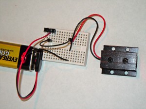
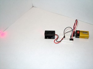
First wire up your laser to a small switch and 9v battery, as pictured below:

Laser with switch Laser with switch

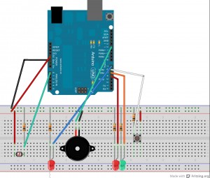
Next wire up the detector, indicator lights and siren according to the diagram below:

This image was made with Fritzing 0.7.11

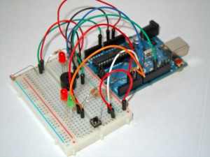
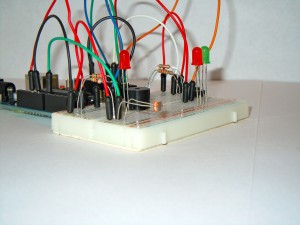
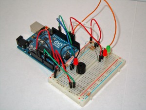
When finished it should look something like this:

Finished laser trip wire Finished laser trip wire Finished laser trip wire

Finally, load the following code into your Arduino sketch, upload to your Arduino board, tweak if you need to and test. This code can also be found on github.

/*
 * Laser trip wire
 * v 1.3
 * by: Keith Kay
 * 1/31/2013
 * CC by-sa v3.0 - http://creativecommons.org/licenses/by-sa/3.0/
 * https://keithkay.com
 * 
 * Laser trip-wire sketch which implements the following functionality: 
 * - Calibration to current light environment
 * - Visual feedback on alignment
 * - Arming and disarming mechanism
 *
 * attribution: siren code modified from
 *   Annoying siren
 *   CC by-sa v3.0
 *   http://tronixstuff.wordpress.com
 * 
 */

// first define the constants used for sensor / emitter pins
const int triggeredLED = 7;  // pin for the warning light LED
const int RedLED = 3;        // pin for the 'armed' state indicator
const int GreenLED = 4;      // pin for the 'un-armed' state indicator
const int inputPin = A0;     // pin for analog input
const int speakerPin = 12;   // pin for the speaker output
const int armButton = 6;     // pin for the arming button

// define variables used for readings and programatic control
boolean isArmed = true;      // variable for the armed state
boolean isTriggered = false; // has the wire been tripped
int buttonVal = 0;           // variable to store button state and compare with previous
int prev_buttonVal = 0;      // variable to 'debounce' button
int reading = 0;             // variable to store the analog value coming from the sensor
int threshold = 0;           // variable set by the calibration process

// constants used for the siren
const int lowrange = 2000;   // the lowest frequency value to use
const int highrange = 4000;  //  the highest...

void setup(){

  // configure LEDs for output
  pinMode(triggeredLED, OUTPUT);
  pinMode(RedLED, OUTPUT);
  pinMode(GreenLED, OUTPUT);

  //configure the button for input
  pinMode(armButton, INPUT);

  // for debugging and calibration review
  Serial.begin(9600);
  Serial.println("");
  Serial.println("Initializing...");

  // intial 'test' to be sure all LEDs and the speaker are working
  digitalWrite(triggeredLED, HIGH);
  delay(500);
  digitalWrite(triggeredLED, LOW);

  Serial.println("Unarmed");
  setArmedState();
  delay(500);

  Serial.println("Armed");
  setArmedState();
  delay(500);  

  // calibrate the laser light level in the current environment
  // this was moved to a function for future integration of a reset function
  calibrate();

  // start unarmed
  setArmedState();  

}

void loop(){

  // read the LDR sensor
  reading = analogRead(inputPin);

  // check to see if the button is pressed
  int buttonVal = digitalRead(armButton);
  if ((buttonVal == HIGH) && (prev_buttonVal == LOW)){
    setArmedState();
    delay(500);
    Serial.print("button val= ");
    Serial.println(buttonVal);
  }

  // print the value to serial
  Serial.print("Reading = ");
  Serial.println(reading);

  // check to see if the laser beam is interrupted based on the threshold
  if ((isArmed) && (reading < threshold)){
    isTriggered = true;}

  if (isTriggered){

    // siren code
    // increasing tone
    for (int i = lowrange; i <= highrange; i++)
    {
      tone (speakerPin, i, 250);
    }
    // decreasing tone
    for (int i = highrange; i >= lowrange; i--)
    {
      tone (speakerPin, i, 250);
    }

    // flash LED
    digitalWrite(triggeredLED, HIGH);
    delay(10);
    digitalWrite(triggeredLED, LOW);

  }

  // short delay - if you are debugging a modification you may want to increase this to slow down the serial readout
  delay(20);

}

// function to flip the armed state of the trip wire
void setArmedState(){

  if (isArmed){
    digitalWrite(GreenLED, HIGH);
    digitalWrite(RedLED, LOW);
    isTriggered = false;
    isArmed = false;
  } else {
    digitalWrite(GreenLED, LOW);
    digitalWrite(RedLED, HIGH);
    tone(speakerPin, 220, 125);
    delay(200);
    tone(speakerPin, 196, 250);
    isArmed = true;
  } 
}

void calibrate(){

  int sample = 0;              // array to hold the initial sample
  int baseline = 0;            // variable to set the baseline reading
  const int min_diff = 200;    // minimum difference needed between current light level and laser calibration
  const int sensitivity = 50;
  int success_count = 0;

  // ensure both LEDs are off
  digitalWrite(RedLED, LOW);
  digitalWrite(GreenLED, LOW);

  // start by taking a 10 reading sample, then take the average for our baseline
  for (int i=0; i<10; i++){
    sample += analogRead(inputPin); // take reading and add it to the sample
    digitalWrite(GreenLED, HIGH);
    delay (50); // delay to blink the LED and space readings
    digitalWrite(GreenLED, LOW);
    delay (50); // delay to blink the LED and space readings
  }

  // calculate and print the baseline
  baseline = sample / 10;
  Serial.print("baseline = ");
  Serial.println(baseline);  

  // now keep taking a reading until we've gotten 3 successful reads in a row
  do
  {
    sample = analogRead(inputPin);      // this time we work with one reading at a time

    if (sample > baseline + min_diff){
      success_count++;
      threshold += sample;

      digitalWrite(GreenLED, HIGH);
      delay (100);                     // delay to blink the LED and space readings
      digitalWrite(GreenLED, LOW);
      delay (100);                     // delay to blink the LED and space readings
    } else {
      success_count = 0;               // this give us the 'in a row' result
      threshold = 0;
    }

  } while (success_count < 3);

  //lastly we need to correctly set the threshold as it now hold the sum of 3 samples
  threshold = (threshold/3) - sensitivity;

  // play the arming tone and in reverse and print the threshold to condfrim threshold set
  tone(speakerPin, 196, 250);
  delay(200);
  tone(speakerPin, 220, 125);
  Serial.print("baseline = ");
  Serial.println(baseline);

}

For an overview of how this functions, I have included a video walkthru on youtube

At this point, this is as far as I am going to take this, but would love to hear ideas that build on this.