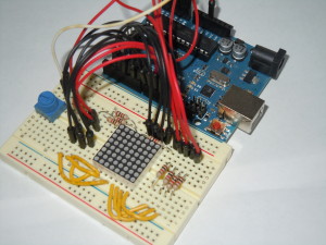
This project is an 8×8 LED Matrix bitmap driven display. One day while shopping on Adafruit for parts for a different project, I became fascinated with LED Matrixes they have for sale, and had a number of ideas for projects including a one letter at a time ticker-tape, and this project which is inspired by the old-fashion flip books like ones I would make in the corner of my notebooks when bored in class. I liked the notion of the challenge of having to design graphics that could only be represented in an 8×8 display. There’s something nostalgic about it. At any rate I hope you enjoy making this, and would love to see what bitmaps you come up with if you feel like sharing them.
What you’ll need for this project:
- Arduino Uno
- Medium breadboard
- 8×8 LED Matrix (I used this one from Adafruit, but did not solder on the backpack yet)
- Potentiometer (I used a 10k)
- 8 1k Ω resistors
- 18 jumper wires
- 8 small pieces of hookup wire, trimmed (or additional jumper wire if you prefer)
I faced two main problems in getting this project to work. The first was figuring out which PINs lit up which rows and columns on the matrix. It turns out I couldn’t find a “standard” pin-out diagram, but I noticed from the picture on Adafruit for the part only half the pins on each side had a resistor, so that’s how I wired mine up. From there I went through the process of powering the matrix pin by pin to figure out the set up.
Once you have it wired up, it should look something like this:
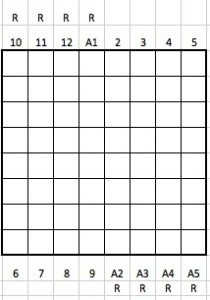
I am using A0 for the pot input (you will also need to connect it to a GND and 5v), and A1 to A5 correspond to digital output 15 to 19 (the Arduino analog pins can also be used as addition digital pull up resistors.) The wire diagramming tool I use didn’t have the graphic for the LED matrix, so I mapped the Arduino pins to the matrix below. The ones with an “R” need to have a resistor between the Arduino pin and the matrix pin.
You can test your wiring with this simple sketch that will light up one LED at a time, then progress column by column row by row. If the LEDs are not lighting up in order, then change the order in columnPins and rowPins until they do.
const int columnPins[] = { 6, 7, 8, 9, 2, 3, 4, 5 };
const int rowPins[] = { 15, 12, 11, 10, 19, 18, 17, 16 };
int row;
int col;

void setup() {

  for (int i=0; i<8; i++) {

    // set each pin to output
    pinMode(columnPins[i], OUTPUT);
    pinMode(rowPins[i], OUTPUT);

    //ensure each LED is off
    digitalWrite(columnPins[i], HIGH);
    digitalWrite(rowPins[i], LOW);

  }
}

void loop() {

  for (row = 0; row < 8; row ++) {
    digitalWrite(rowPins[row], HIGH);
    for (col = 0; col < 8; col++) {
      digitalWrite(columnPins[col], LOW);
      delay(100);
      digitalWrite(columnPins[col], HIGH);
    }
    digitalWrite(rowPins[row], LOW);
  }
}
The second issue was the time it takes, and the likelihood of making a mistake, in designing bitmaps by hand in the Ardunio sketch, 0 by 1. Especially since my goal was to make multi-frame movies. My solution to this was to develop a Processing program that would allow me to visually design each frame and save it to a file, which is described in a separate post.
Finally, load the following code into your Arduino sketch, upload to your Arduino board, and be sure to add your own set of bit maps (though you can use the one below in the code of course). This code can also be found on github along with a few example bitmaps.
/*
 * LED Matrix Bitmap Display v2
 *
 * by: Keith Kay
 * 11/27/2013
 * CC by-sa v3.0 - http://creativecommons.org/licenses/by-sa/3.0/
 * https://keithkay.com
 *
 * This sketch displays a bitmap or series of bitmaps on a 8x8 LED matrix, and implements the following
 * functionality:
 * - supports a variable number of frames as defined by the constant "frames"
 * - use of a potentiometer to control the frame rate
 *
 * Portions of this code from:
 *
 * “Arduino Cookbook, Second Edition"
 * by Michael Margolis with Nick Weldin (O’Reilly). Copyright 2012 Michael Margolis, Nick Weldin,
 * 978-1-4493-1387-6
 *
 */

// Note that if you are using Keith's "Processing Bitmap Generator for Adruino" you need to move the "frames"
// declaration up before the array, as it will be the last thing written to your bitmap file.

// <-- Copy and paste your bitmap array beginning here, or you can write it from scratch -->>

const int frames = 16; // Constant defining the number of frames

byte imgFrame[frames][8] = {
{   B11111111,B10011001,B10011001,B11111111,B11100111,B11000011,B11011011,B11111111}, // Each row here represents one frame
{   B11111111,B10011001,B10011001,B11111111,B11100111,B11000011,B11011011,B11111111},
{   B11111111,B10011001,B10011001,B11111111,B11100111,B11000011,B11011011,B11111111},
{   B11111111,B11111111,B10011001,B11111111,B11100111,B11000011,B11011011,B11111111},
{   B11111111,B11111111,B11111111,B11111111,B11100111,B11000011,B11011011,B11111111},
{   B11111111,B11111111,B10011001,B11111111,B11100111,B11000011,B11011011,B11111111},
{   B11111111,B10011001,B10011001,B11111111,B11100111,B11000011,B11011011,B11111111},
{   B11111111,B10011001,B10011001,B11111111,B11100111,B11000011,B11011011,B11111111},
{   B11111111,B11111111,B10011001,B11111111,B11100111,B11000011,B11011011,B11111111},
{   B11111111,B11111111,B11111111,B11111111,B11100111,B11000011,B11011011,B11111111},
{   B11111111,B11111111,B10011001,B11111111,B11100111,B11000011,B11011011,B11111111},
{   B11111111,B10011001,B10011001,B11111111,B11100111,B11000011,B11011011,B11111111},
{   B11111111,B10011001,B10011001,B11111111,B11100111,B11000011,B11011011,B11111111},
{   B11111111,B10011001,B10011001,B11111111,B11011011,B11011011,B11000011,B11111111},
{   B11111111,B10011001,B10011001,B11111111,B11011011,B11011011,B11000011,B11111111},
{   B11111111,B10011001,B10011001,B11111111,B11011011,B11011011,B11000011,B11111111},
};

// <-- End copy and paste. Make sure you overright the array already here -->>

// define the constants used for sensor / emitter pins
const int columnPins[] = { 6, 7, 8, 9, 2, 3, 4, 5 };      // array holding the pin numbers of the rows
const int rowPins[] = { 15, 12, 11, 10, 19, 18, 17, 16 }; // array holding the pin numbers of the columns
const int potPin = A0; // potentiometer

// define variables used for readings and programatic control
int row;
int col;
int potVal;
int frameDelay = 0;
int currentFrame=0;

void setup() {

  for (int i=0; i<8; i++) {

    // set each pin to output
    pinMode(columnPins[i], OUTPUT);
    pinMode(rowPins[i], OUTPUT);

    //ensure each LED is off
    digitalWrite(columnPins[i], HIGH);
    digitalWrite(rowPins[i], LOW);

  }
}

void loop() {

  potVal = analogRead(potPin);    // read the voltage on the pot
  frameDelay = map(potVal, 0, 1052, 1000, 50);

  if (currentFrame < frames) {
    show(imgFrame[currentFrame++], frameDelay);
  } else {
    currentFrame = 0;
  }
}

void show( byte * image, unsigned long duration) {

  unsigned long start = millis();        // begin timing the animation
  while (start + duration > millis())    // loop until the duration is reached
  {
    for (row = 0; row < 8; row++ )
    {
      digitalWrite(rowPins[row], HIGH);  // connect a whole row to +5v
      for (col = 0; col < 8; col++)
      {
        boolean pixel = bitRead(image[row], 7-col);
        if (pixel == 1)
        {
          digitalWrite(columnPins[col], LOW);  // connect column to grnd
        }
        delayMicroseconds(300);    //small delay for each LED
        digitalWrite(columnPins[col], HIGH);  // disconnect column from grnd
      }
      digitalWrite(rowPins[row], LOW);  // disconnect a whole row
    }
  }
}
When it’s finished you should be able to load different bitmaps and display them, as these examples show.


Hi Thanks for your hard work. I have wired my own 8×8 led display and this code has helped a lot as I had a couple of cold joints that were hard to find. Thanks, I will try to post some pics if I can
Phill